Our design is based on an idea about sustainable and innovative approaching to the main topic.
As a house as a home, a forest is uniq and special place for years for the living beings. Thinking ofparent cluster, forest is a house for us which fed by water. Life moves on around water.Every family member of the forest need water to survive. Being a part of a forest starts with being a part of water. As a conceptual idea we wanted to cling on the fountain of the forest. The powerful movement of a river in a forest is the key of the project.
The movement of a river is the most powerful energy in a forest comes out by nature. This power of movement of a river observed exahustive and analysed by Rhino+Grasshopper. As a result of this motion we mapped of the water of the river. This mapping are explaning the water movements and routes. Thus shaping of the river by this routes let us to see, how to get maximum surface area by this tracks. These surfaces have maximum friction surface under water we can use this power to occur the energy comes by river movement.
Obstacles in the river like a tree or a rock, shapes water around. We used this points to create house areas to use. Also getting maximum sunshine to the house is possible with location and the best location is an open area like water elements. As a material of construction wood elements and stone we used as a part of forest.
Living in a forest alone is not realistic, being a uniq house piece of forest is not being a part of forest. With this approaching we created a community, neighbourhood and creating new living spaces for other livings in forest. There are 4 housing zones to live and there are small livings spaces for other neighbours like small creatures.
Following the shapes of the water creates potential of right air way comes from forest and river.In addition of them acting form of the house like river dont blocks the water flowing and being in the river by surfaces let the control of the water resistance.
Project Team
Ersin Abay
Cansu Yeni
4 Nisan 2017 Salı
23 Aralık 2016 Cuma
Dynamo Study 4 - Facade Rationalization
This article is from my last course before the thesis (unfortunately turkish).
8 Aralık 2016 Perşembe
6 Aralık 2016 Salı
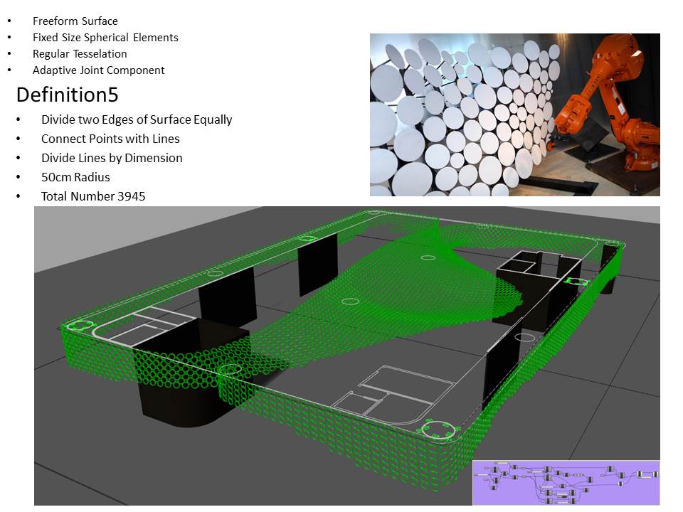
Freeform Surface Panelling
This was a ceiling modelling study that I worked on in the office. The
ceiling has double curvature surface which is bending from facade to ceiling
and ceiling to facade. Also the designer wanted to have the surface covered
with hollow round modules. Then I started looking for computational solutions
in grasshopper.
There was only one constrain and that was to keep the
surface of the ceiling (the freeform shape). Panelling algorithm changes in
each material and each fabrication method. We needed an optimisation strategy
to find an easy production and implementation method. Budget was also an
important factor (as usual :).
I searched many materials, many connection details, many
construction methods and many surface partition algorithms to be able to build
this ceiling.
The research period was informative for me. You can find
some applied panelling examples and related partition algorithm that I tried
below.
Thank you for reading.
Cansu
22 Eylül 2016 Perşembe
The UnLimbited Arm
Making a hand is so easy with a 3D printer anymore. All informations and 3D model at below links. Here you can see my "UnLimbited Arm" study. I thank for Osman Koç and Robotel Team for their help.
https://www.youtube.com/watch?v=369PX9LzUPs
20 Eylül 2016 Salı
Dynamo Study 3 - Facade Rationalization
Setting Adaptive Components in Revit
Scheduling Panel Corner Angels
Grasshopper Panel Connection Detail
Dynamo Panel Connection Detail
Grasshopper Panel Connection Detail
Dynamo Panel Connection Detail
These panels modeled with "extrusion" command in Grasshopper. Adaptive Family works like "sweep" command, because of this, panels move over the alignment.
List Tansformation for Panelling
Glass Panel Array
Etiketler:
additive manifacturing,
architectural design computing,
bim,
blm,
building information modelling,
Design Scripting,
Development environment,
dynamo,
interoperability
6 Eylül 2016 Salı
Dynamo Study 2 - Facade Rationalization
This facade consists of the combination of a rectangle and a 8 sided star. This computational logic allows to study it in algorithmic environment.
Grasshoper Script
Facade Rationalization process have been done at Rhinoceros- Grasshopper. Optimization process forge ahead between facade consultant and designer.
I wanted to follow up all process in BIM environment step by step. I am looking for the differences between CAD & BIM environment in Rationalization process. Is BIM has an advantage during rationalization process for computational cases?
Initial Geometry
Main Horizontal Alignments
Surface normal disjointedness
Curve selection rule
Facade Trigon and Tetragon Paneling
It is certain that this topic has extended research area. I keep reading and continue to experiment about it. I will create new titles based on them...
Thank you for reading.
Cheers,
5 Eylül 2016 Pazartesi
Dyno Tool - Something Inteesting is Happening
Take a look to Dyno, It looks exciting.
"Dyno provides versatile and simple possibilities for making work with Dynamo workspaces faster."
http://tools.prorubim.com/en/dyno/
User Manual
http://tools.prorubim.com/en/dyno/docs/
Etiketler:
add-in,
algoritmic design,
bim,
building information modelling,
collobrative design,
Development environment,
dynamo,
dyno,
interactive design,
interoperability,
research&development,
revit,
revitAPI,
software
Dynamo Study 1 - Coordination between ARCH&MEP
Architects are still modeling MEP equipment in their own architectural
Revit model, even though it is a BIM project in order to be coordinated with
MEP. This method can also be argued to being not feasible, but was one I
used for coordination in a Residential Building Project.
We have been
modelling all ceiling equipment to manage ceiling layout on
Architectural BIM models, like lighting, sprinklers, detectors..etc.
Essentially Mechanic Engineers modelling these equipment into BIM model,
because of that reason we had to check all equipment if they exist or are in
the right location to be able to provide coordinated layout after every model
share.
Following this, I
decided to compare the equipment location between Architectural and MEP models
with using Dynamo.
The first problem was architectural and
MEP model's mismatches, Architect separating tower blocks and podium floors
into different model files, MEP separating different mechanical systems (HVAC,
Security System, Water Supply System, Fire Alarm...) into different model
files. The reason, I had to link all the models into one model with using
"Get elements From Linked Model" node , than catch the family centre
points.
Ensuring tolerance despite small slip.
Second problem was the "shared coordinate data" which were different in all the BIM models. Accordingly, I manually transferred all points in each model to the same coordination point.
Transfer the points to the Same Coordinate System
After transferring elements manually this problem solved in Dynamo Forum. There is a topic which is solved by Dimitar_Venkov It is explaining how to transfer linked elements to the "shared coordinate" location.
https://forum.dynamobim.com/t/querying-a-linked-model-and-creating-from-it/1052/12?u=jesper_wallaert
The link below will take you to the dynamo forum where I was helped to match close points in the model. I matched the points as you can see below in the excel sheet. If there was a point less than 1000mm away, dynamo wrote it down on the side column, if there was no point it left the side column empty. After that I could determine which location had the problem.
These clashes can be provided with this dynamo study and coordination has become easier.
Thank you for
reading.
Cheers,
Kaydol:
Kayıtlar (Atom)